The second-generation Eurocode 2 and the sandwich method
The second-generation Eurocode 2 makes the sandwich method normative for the design of shells and slabs. Here is what the method is, what changes, and why transparency matters more than ever.
Most reinforced concrete walls and slabs in a finite element model carry more than one action at once: in-plane forces, bending and twisting moments, and out-of-plane shear. Designing an element for all of them together, consistently, for every load case, is exactly the problem the sandwich method solves. With the second-generation Eurocode 2, that method becomes normative for shell and slab design, with the switchover expected in 2028.
What the sandwich method is
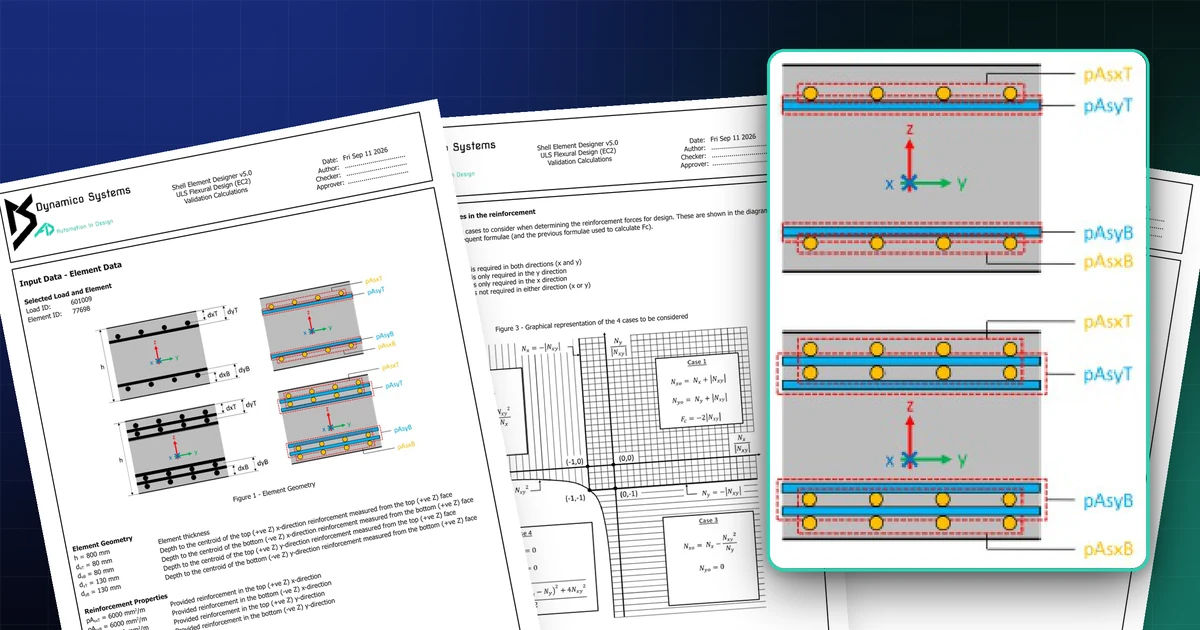
The method idealises each shell element as three layers. The two outer layers carry the membrane forces and moments, converted into in-plane forces in each layer; the inner core carries the out-of-plane shear. Each outer layer is then designed as a membrane: the reinforcement needed in each direction follows from the layer forces, and the concrete in the layer is checked in compression.
The engineering is in the details. The thickness of each outer layer has to be chosen and then verified, because it sets the lever arm between the layers. When one direction needs no reinforcement, the concrete force redistributes, and the equations change. Most published presentations organise this into four cases, depending on whether reinforcement is needed in both directions, only one, or neither.
What changes with the second generation
Today, the sandwich approach for shells appears in Eurocode 2 as informative guidance, in the concrete bridges part. Designers can use it, and many do, but the approach and its assumptions vary from office to office. Making it normative means one consistent method for walls and slabs, and it means checkers and clients will increasingly expect to see that method, and its intermediate steps, in the calculations.
Why transparency matters more
A method with layer thicknesses, redistributed forces and four cases is easy to get subtly wrong and hard to check from a single output number. The answer is not to hide it behind a black box, but to show every step. In Shell Element Designer, the validation calculation for any element and load case sets out:
- the element geometry and material properties used;
- the applied forces and moments, with the sign convention;
- the calculated and verified layer thicknesses;
- the sandwich forces in each layer, and the case that applies;
- the required reinforcement in each direction and face, and the utilisation ratios.
Because the sandwich method is already the core of the software’s Eurocode 2 and code-independent design, the switchover changes little for its users: the method, and the evidence for every number, are already there. See the validation calculations on the product page.