
Shell Element Designer
Automated, code-compliant design of reinforced concrete walls and slabs, with mathematical reinforcement optimisation, 3D IFC export and AI integration over MCP. Every element, every load case, with the working on the table.
The real workflow in 18 seconds: module → input files → 35,066 elements designed → verified results summary.
Your analysis finishes.
Your design begins automatically.
Shell Element Designer takes completed analysis results from any package and performs full code-compliant design of reinforced concrete walls and slabs: required reinforcement, utilisation ratios, crack widths and deflections, for every element, for every case, in one run.
Shell Element Designer performs design on completed analyses. It does not perform structural analysis.
Flexural reinforcement
In-plane longitudinal reinforcement design with required areas and utilisation ratios.
Eurocode 2 Parts 1-1 & 2 · ACI 318M · ACI 349M · AFCEN RCC-CW · Brondum-Nielsen 1974 · Clark & Cope 1984
Shear reinforcement
Out-of-plane shear design with required areas and utilisation ratios.
ACI 318M (incl. 318M-19 size effect) · ACI 349M · AFCEN RCC-CW · Eurocode 2 WIP
Crack width checks
Serviceability checks against code and user-specified limits, with utilisation ratios.
Eurocode 2 Part 1-1 · AFCEN RCC-CW
Long-term deflections
Long-term deflection checks against code and user-specified limits.
ACI 349M · Eurocode 2 WIP
Provided reinforcement check
Assess the reinforcement you have actually provided against what every element requires, from a provided-reinforcement file you write yourself or generate in the Reinforcement Applicator.
Reinforcement Applicator
Turn required reinforcement into buildable bar layouts on every panel, drawn by hand or generated by automated mathematical reinforcement optimisation.
The only commercially available automated post-processing design tool spanning European, US and French (nuclear) design.
Switch design codes by adjusting the input files, and run the same model to multiple codes for true element-by-element comparisons.
Eurocode 2
BS EN 1992-1-1 and Part 2 (bridges). Ready for the second-generation EC2, which makes the software’s core sandwich method normative for shells and slabs from 2028.
ACI 318M / ACI 349M
US building code and the nuclear safety-related concrete code, including the ACI 318M-19 size-effect modification for shear.
AFCEN RCC-CW
The French rules for design and construction of PWR nuclear civil works (2023 edition, previously ETC-C): flexural, shear and crack width modules with validation calculations.
Code independent
The Clark-Nielsen sandwich method, available on every edition, plus a Utilisation Ratio module that checks provided against required reinforcement. Design from first principles, independent of any national code.
Patented recognition
Walls and slabs are recognised automatically from bare model geometry by our patented, rule-based AI automation methodology. No machine learning, no training data, repeatable results.
All 8 forces & moments
Full shell design under membrane forces, bending moments, twisting and out-of-plane shear, including 250M+ unsymmetrical interaction curves on a single production project.
What every design run covers.
The detail behind ‘every element, every case’: what the engine reads, what it designs for and what you control, element by element.
- Triangular and quadrilateral shell elements
- Membrane and bending actions together on every element, on both faces and in both directions, including twisting
- Multiple load combinations in one run, with the governing case reported for every element and direction
- Symmetrical or unsymmetrical reinforcement per element in ACI flexural design
- A per-element reinforcement search in ACI flexural design, from a start to an end percentage in steps you set
- Per-element materials and partial factors for every design module
- Bar spacing, layer count, cover and bar diameter per element for crack widths
- Long-term deflections from a per-element deflections file for each load
- Sign conventions and units to match your analysis package, so its results are read directly
- No limit on elements or load cases
An interface that checks your work before you run it.
One modern interface in a branded, frameless window with Windows 11 snap layouts and rounded corners. On smaller screens the sidebar collapses to an icon rail, so your work keeps the room.
Guided from the first launch.
The User Manual opens itself the first time you start the software, and a guided tour walks you round the interface.
- The EzyWizard: ten numbered steps from input files to results, with a plot example page and a Bolt-On launcher
- A Help page that opens the User Manual, the Verification Manual, Report an Issue and About
- The Reinforcement Applicator has its own nine-step interactive guide, a Change Files button and confirmation dialogs that protect unsaved work
Your licence at a glance.
The dashboard opens with an update banner and a release-notes feed, so you always know what changed and when.
- Usage statistics synced from the licence server for the whole licence: on a floating licence they add up every user’s runs
- Elements designed, design time and plots produced, with a Time Saved estimate
Every file checked before you press Process.
Select your input files and the software checks them in the background, with a plain-language verdict for each file and across the whole set.
- A readiness meter showing how close the run is to ready
- Size and date chips on every file, so you know you picked the right version
- One-click clear to start again
Every setting explains itself.
Cover, reinforcement layers, materials and design options live in one set of Advanced Options, and each shows a live one-line note saying exactly what it will do.
- Sign convention and units chosen to match your analysis package
- Plot and load-combination options set before the run
Watch every step as it happens.
The run console narrates each step live, with per-step timings and a progress ring, and a Stop button if you need it.
- Multi-threaded engines that scale with faster processors and higher thread counts, such as AMD Threadripper
- Every run writes to a fresh, date-stamped results folder beside your inputs, so nothing is ever overwritten
- An Open Results Folder button the moment it finishes
A record of every run.
Run history keeps every run’s counts, timings and warnings, and survives restarts.
- Spot a slow run or an unexpected warning at a glance
- Clear it card by card, or all at once
Ask your results a question.
The Results page reads any results file and answers four questions: which element governs, the top five, how many exceed a limit, and the full row for one element.
- Sensible default limits for each result type, and no limit on file size
- A file fingerprint, so every summary is tied to exactly one version of one results file
- Save the summary as a standalone page, or open it in your browser
Human-readable in.
Human-readable out.
Inputs are plain text files you can diff, review and version-control like any engineering record. Every format is documented, Excel templates come with the installation, and every file accepts comment lines for your own notes. Outputs are the same: the complete results data for every step of the design, free for you to use in any downstream application.
The open .dys format
Every Ultimate design run writes an open, XML-based .dys 3D model file. Open it in the Design Visualiser, parse it with a script, archive it with the project. Nothing is locked away.
- Plain, self-describing structure: headers state module, version, units and sign convention
- Every plot variable for every element, exactly as designed
- Your data outlives any single software vendor
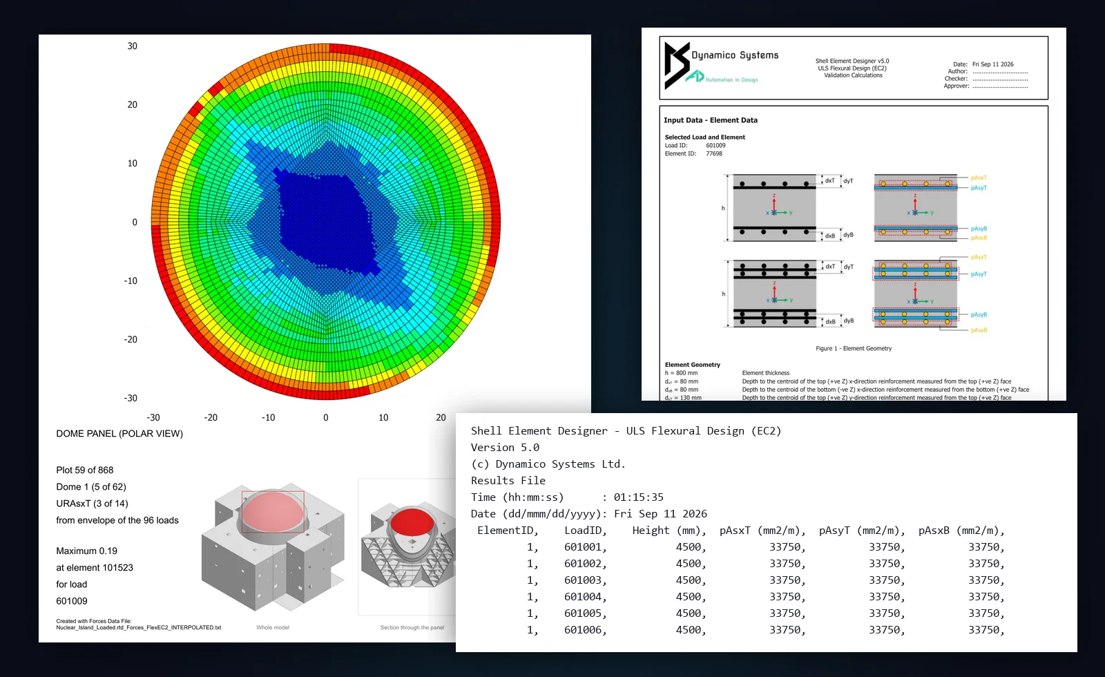
PDF plots, ready to issue
Graphical contour plots are produced automatically for every panel and every design variable, with maximum-value call-outs, local axis labels, and a customisation file for your own header, footer, logo, author, checker and document numbers.
- A shaded 3D picture of the whole model on every page, with the plotted panel in red
- The maximum value on every page, with its element and governing load
- Colour-scale limits you set per plot, and automatic panel names for cylinders, domes, curved and skew panels
- An editable automatic plot file you can reuse on the next run
- Design errors and out-of-scale values highlighted automatically
- Very large plot sets split automatically into parts with continuous page numbering
Results files
Every run writes a results file with documented columns for each module and a log file of the whole run, plus an Ansys-compatible results file for teams working with very large models on highly complex projects.
Comprehensive user manual
A fully detailed user manual walks you through every feature, input file and process, written by engineers who worked in industry, for engineers who work in industry. It installs with the software as a searchable Windows help file (CHM) with contents and a keyword index, plus a glossary, nomenclature for each module, a worked example, FAQs, troubleshooting, What’s New and system requirements.
Verification manual
Design modules are verified against worked design examples from the literature, and the evidence ships with the software: a manual of hand calculations, 300+ automated tests and 18 regression checks on every release.
Any element. Any case.
Working like a hand calc.
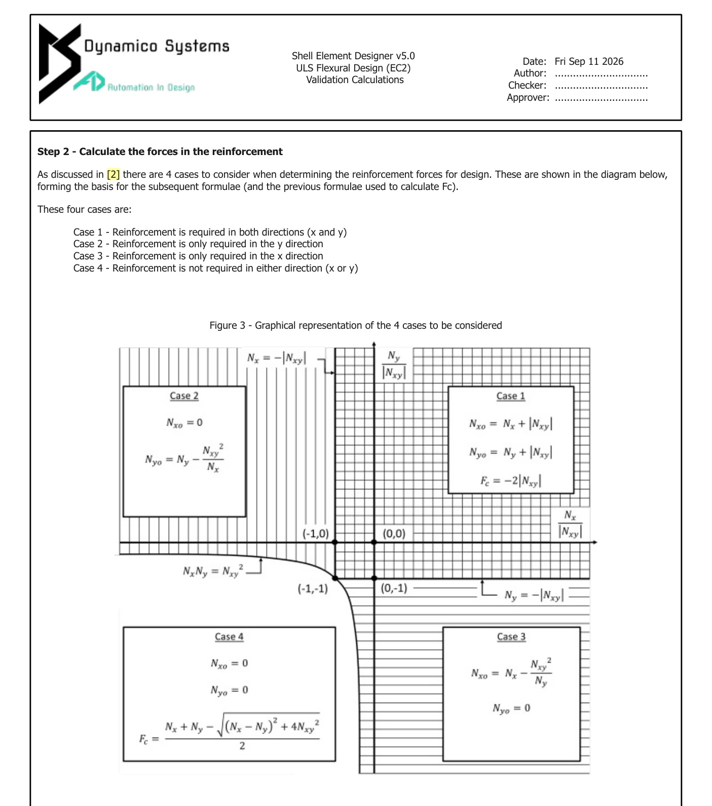
Pick any element and any load case, and Shell Element Designer produces a step-by-step validation report: a 12-page PDF that lays out the full calculation in hand-calc style, with the governing case, the code clauses, every intermediate value and interaction-curve figures.
- An audit trail a nuclear regulator can follow, and has. Designs produced with the software have passed independent technical assessment and have secured ONR approval
- Perfect for independent checkers and category 3 checks
- Customisable header, author, checker and reviewer fields
From required reinforcement
to buildable zones.
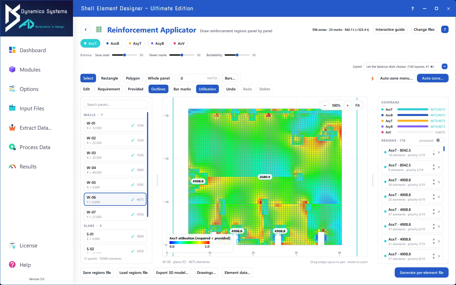
The software builds your walls and slabs from bare element and node data, grouping them automatically into walls, slabs, skew and curved panels, then lets you turn required reinforcement into bar layouts panel by panel, drawn by hand or zoned automatically using automated mathematical optimisation, against a live map of demand.
Draw on the demand
Five layers, the four flexural faces and directions plus shear links (AsxT, AsxB, AsyT, AsyB, AsV). Switch between requirement, provided and utilisation heatmaps, with per-element tooltips showing needed versus provided.
Full coverage, gated
Coverage is tracked live for every layer, and every apply re-runs the full safety contract: complete coverage and provision ≥ demand on every element, or it refuses.
Files, not lock-in
Regions save and load as open files, and one click generates the per-element provided-reinforcement file for the design modules. Undo, redo, repeat.
Curved structures
Curved walls, drums, cones and domes are laid flat one panel at a time. Hoops become single bars closing into rings, seams come from the mesh, developed sheets carry true bar lengths, and zoning works in bands and sectors.
Always oriented
A panel browser grouped into walls, slabs, curved and skew panels, with search and per-panel tooltips, and a resizable 3D context picture in the canvas corner showing where you are in the structure.
Tools that feel right
Select with handles, draw rectangles with corner snapping, polygons or whole panels, and set region priority. Undo, redo and keyboard shortcuts throughout, plus a nine-step interactive guide for your first session.
Global reinforcement optimisation, across three objectives.
Unlocked by the patented methodology and proven on Class 1 nuclear projects, the Auto-Zoner proposes complete zonings automatically, searching a catalogue of real bar layouts for the exact optimum, not a heuristic guess.
Save steel
Minimise surplus provision above demand, cutting material cost and embodied carbon on every panel.
Fewer marks
Minimise the number of distinct bar layouts across the whole section, for simpler schedules, simpler procurement, fewer site errors.
Buildability
Prefer aligned spacings between neighbouring zones, faces and directions, so the cage that comes out is one you can actually fix.
Deterministic, exact, auditable
The optimiser is a complete branch-and-bound search over real bar layouts from your chosen bar-mark set: Default, Extended up to H50 with bundled pairs, or Custom over the full 200-row catalogue, editable in the app with a bar helper that converts diameter and spacing to area. It returns the exact optimum under your weighting: identical inputs give identical answers, byte for byte. No randomness, no clock, no drift.
You hold the dials
Balance the three objectives with live sliders and watch the zoning re-select instantly, or browse every layout the structure can be built with, each listing its zones, bar marks and tonnage. Elements that no permitted layout can satisfy are never silently patched. They are named, marked on the canvas and require explicit engineer consent.
Every run works without a single click.
Everything the interface does, the command line does too: module, inputs, options and outputs as plain arguments, exit codes you can script against, and byte-identical results for identical inputs. Headless running is the foundation that makes automation, and AI, possible.
Batch pipelines
Chain design runs, reinforcement application and exports in scripts or CI. Rerun a whole project overnight, or a whole portfolio.
Deterministic to the byte
Identical inputs give byte-identical output files, so pipelines can diff runs, pin baselines and prove nothing changed.
The gateway to AI
Because every capability is callable without the interface, AI assistants can drive real engineering workflows, while the deterministic engine keeps every number honest.
Talk to your design runs. [Beta]
Shell Element Designer includes an MCP (Model Context Protocol) server with nineteen tools, so AI assistants such as Claude and Codex can work with the software in plain English: prepare inputs, run designs, apply reinforcement, export models and interrogate the results. Built on the headless engine, with one rule: the AI orchestrates, the deterministic engine calculates.
Run designs
Start design runs, check their status, cancel them and look back through the run history, all from the conversation.
Prepare inputs
Stage and write input files, with a receipt for every file written, so you can see exactly what the assistant changed.
Reinforce and export
Apply reinforcement and export the IFC and Tekla models without leaving the chat.
Ask the results
Query any completed run and ask questions of it: the governing element, the count over a limit, a full summary.
Check claims
Check a statement about the results against the results file itself before it goes into a report.
Manuals on hand
The User Manual and the Verification Manual are both served to the assistant, so answers about the software come from its own documentation.
You stay in charge
Before anything runs, a human approval gate shows the plan in your own words, and no default is ever assumed. Every engineering value still comes from the same deterministic engine as the interface.
- Long runs outlive the tool call: a browser tracker page follows progress and a tray notification announces the end
- Numbers are quoted verbatim from the results file and tied to its fingerprint
- IT can disable the server, or only its run tools, by registry policy
From design results to BIM-ready models.
A design run doesn’t end at numbers. Auto-zoned reinforcement becomes real, individual bars in 3D, exported to open formats your BIM workflow already understands.
3D IFC export
Reinforcement zones become individual bars in real 3D coordinates, written as IFC4 with a project, site, building and storey tree, one assembly per panel and patch, concrete as walls and slabs, and property sets on every bar and panel. Curved walls become single revolved solids with openings cut as voids. Every file is read back and verified, and a file that fails is deleted rather than handed over.
Tekla export [Beta]
Native Tekla Structures rebar through Trimble’s Open API, with the concrete optional, grade, material, class and name options, work-plane handling and traceability properties on every bar.
Checking drawings [Beta]
PDF checking drawings with developed elevations, bar-mark labels, patch schedules and seam marks, a 3D context picture on every sheet, a splices-and-spacing note, and red warnings for anything leaving the concrete. Choose every bar or one line per patch; large sets split automatically.
Export report
Every export reports its bar count, metres and tonnes, lists any warnings and refusals, and writes handoff files for your detailing package.
Open .dys model
The transparent 3D results file behind the Design Visualiser: plain, self-describing XML you can archive, diff and parse.
From the command line
The Reinforcement Applicator and its exports run headless too, with every option as a flag and their own exit codes, ready for scripted pipelines.
Built for production workloads.
- Required reinforcement and utilisation ratios
- Multiple reinforcement layers per direction, per face
- Provided reinforcement optional, so you apply it when ready
- No limit on elements or load cases
- Load combinations functionality built in
- Multiple force/moment units and sign conventions
- Multi-threaded runs, up to 90% faster on large sets, scaling with faster and higher-thread-count processors
- Fully headless batch mode for scripted pipelines
- 3D IFC and Tekla [Beta] reinforcement model export
- Automatic log file for every run
Ready for your IT team.
Licensing built for how companies really deploy software, from a single engineer to a floating pool of seats.
- Online activation with a licence wizard
- Offline working for a licensed number of days, tailored to your requirements
- Cloud floating seats, checked back in on exit, with stray-seat recovery
- A second-instance guard, so one seat runs one copy
- Corporate silent activation from a licence-key file, with its own exit codes